Rules of Thumbs about Op Amps:
- No current flows in and out of the inputs
- Op Amp tries to keep the inputs at the same voltage
Rules of Thumbs about Op Amps:
For a non-inverting operational amplifier, the signal enters from the non-inverting pin (+)!, hence the name “non-inverting op amp.”
As such, the closed loop feedback loop travels from the output pin of the op amp to the non-inverting (positive) input pin.
The circuit diagram is as follows:
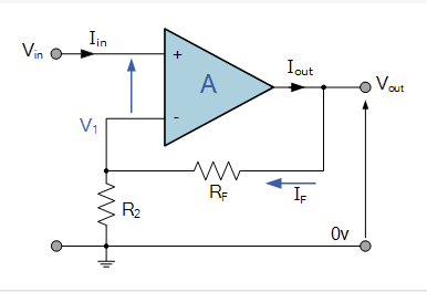
(+) = Non-Inverting Input
(-) = Inverting Input
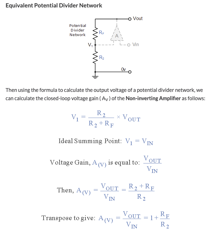
To derive the gain equation, you have to take note of two key observations. Since op amps try to keep the inputs at the same voltage, we know that V_in = V1. Because we also know that no current flows through the inputs, the resistors form a voltage divider network. From here, we can derive the gain equation (A_v)!