The interviewer drew a top and side view of the “home screen”, circular button on the front of an iPhone. If the critical features of the button are the diameter and the position/width of an anti-rotational feature (which was drawn in one of the views), where would you place your datums and critical dimensions. Why? How do you define the datums to reduce the gap and offset between the button and the glass, and the tilt of the icon with respect to the glass?
3 Likes
Admittedly, I’m not the best at GD&T but I will take a stab at the above prompt!
For a basic understanding, let’s zoom out first and understand what Geometric Dimensioning & Tolerancing is all about. When you think about part design, and the intended manufacturer that will actually build said part, GD&T is the language of love (per say) that is spoken to communicate design intent, engineering tolerances, and control the variation in a manufacturing process.
TLDR; how to build a part that exactly matches the on-paper plans in 3-D CAD.
I’ve attached a useful resource that does a great job of explaining GD&T (GD&T Symbols | GD&T Basics).
In the context of above problem, your datums refer to a central plane, axis, or point that dimensional tolerances/features reference back to. Think of it as an anchor point for all dimensions made!
If I were to think of important datums here, one would be from a top view of the home screen referencing the top edge, and using that to locate the home button in X-Y dimensions. For the gap and offset between the button and the glass, it would be from a side view referencing the bottom edge to locate the Z height (variation where the button sits up/down).
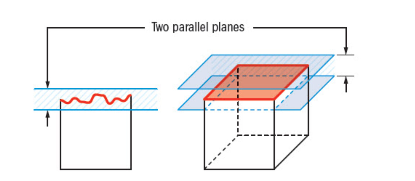
A good way to also ensure the offset between the button and the glass is located at the same height is to call out a flatness specification.
Thinking more about the physical interaction of the button and the glass paneling, critical dimensions to label as CTF (critical-to-function) would be the radial dimensions of the glass cut-out and outer diameter of the button. In order to facilitate a smooth button press, you’ll want a clearance fit with tight tolerances to prevent gaps in your device.
Here is a useful wall-chart as well for explaining the various symbols, four fundamental elements to keep track of, and which tools are used to track certain features.
GD&T Wall Chart.pdf (2.0 MB)
1 Like
I have used GD&T a bit here and there, and would like to take a stab at the problem as well.
Looking at the phone from the TOP view I would use a central imaginary line going through the middle of the phone both for the X and Y axis as datums and give basic dimensions to call out the true position of the buttons midpoint. I would use a diameter callout to specify dia and give a very tight tolerance on this, I would also use a GD&T position callout with the dia. The tolerance for the position should take into the mating part that the button will fix to under the screen. Giving an MMC condition will be helpful, but not sure if giving a bonus MMC tolerance will create more of a gap and aesthetic issue.
For the height and tilt we can use the side view and use the top of the screen as the datum. The button is slightly inset from the top surface which can have a distance callout for the inset and also a flatness callout for the button surface and a parallel callout for the button to the screen surface where the screen will be the control dimension.
Let me know what you guys think!
For context, I’m looking at the phone screen in portrait orientation.
To start, I would say the A datum should probably be the outer surface of the screen. The A datum is that plane because it would be parallel to the sealing surface (which would probably be the inner surface of the screen) and any gap/flush specs would be relative to the outer surface. Since the screen curves downward, using the outer surface is probably also easier from an inspection standpoint.
Next, I would take a look at what the button interfaces with beneath the screen, whether it’s a spring or and actuator or something else, and what the datum features for that are. I would also take a look at the datum features for the screen.
If controlling the eccentricity of the button relative to the actuator/spring is more important than controlling the eccentricity of the button relative to the screen cutout, I would choose the actuator datums. Vice-versa if controlling the eccentricity of the button to the screen cutout is more important.
It’s also possible that eccentricity with the spring/actuator would affect the tilt and that the eccentricity with the screen cutout would affect the gap/offset so choosing datums could be affected by balancing which of those is more important.
Controlling the vertical position of the button is probably more important than controlling the horizontal position (phone is in portrait orientation) since the screen curves about 2mm below the button, but there’s probably more leeway horizontally. So I would choose the B datum to control the vertical position and the C datum to control the horizontal position.
So the A datum is the outer surface of the screen, the B datum is controlling the vertical position (and is either the datum for the spring/actuator or the screen), and the C datum is controlling the horizontal position (and is either the datum for the spring/actuator or the screen).
I would then call out a parallelism constraint between the button and the A datum. I would go for parallelism over flatness because flatness would only control how flat the surface of the button is and not the angle relative to the screen.
Then I would use profile relative to the B and C datums to control the size, shape, and position of the button.
1 Like