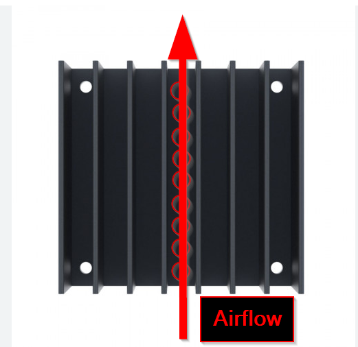
Assuming the airflow across the heatsink as shown, draw a graph depicting the relationship between the pressure drop and the position along the heatsink channel.
The total pressure drop (ΔP) is not just frictional loss along the channels; it is the sum of three parts:
The pressure drop across a parallel plate-fin heatsink isn’t just from the friction in the channels; it’s the sum of three parts:
- Entry Loss: A pressure hit from the air contracting to squeeze into the narrow fin gaps.
- Frictional Loss: The pressure lost to viscous drag as air flows through the length of the channels.
- Exit Loss: Another pressure hit from the air rapidly expanding back out of the heatsink.
The main equation that puts this together is:
ΔP = (ρV²/2) * [ Kc + (f_app * L / D_h) + Ke ]
What this means for design:
- Fin Spacing is King: This is the biggest factor. Tighter fin spacing drastically increases air velocity (
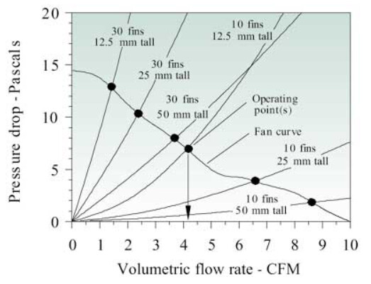
V) and reduces the hydraulic diameter (D_h), which makes the pressure drop skyrocket (it’s proportional to velocity squared!). - It’s a System Thing: You can’t look at the heatsink’s pressure drop alone. It creates a “system curve.” The actual airflow you get is determined by where this curve intersects with your fan’s P-Q curve . A high-pressure-drop heatsink will choke your fan, resulting in lower airflow and worse cooling than you might expect.
In a nutshell: Pressure drop is characterized by minor losses at the inlet/exit and friction through the channels. It’s extremely sensitive to fin spacing and must be balanced with your fan’s capability to ensure adequate airflow.