For bourdon tube pressure gauges, they work by having pressure expand a coil which moves some links and rotates a dial. Here’s some pictures with low/high pressure readings:
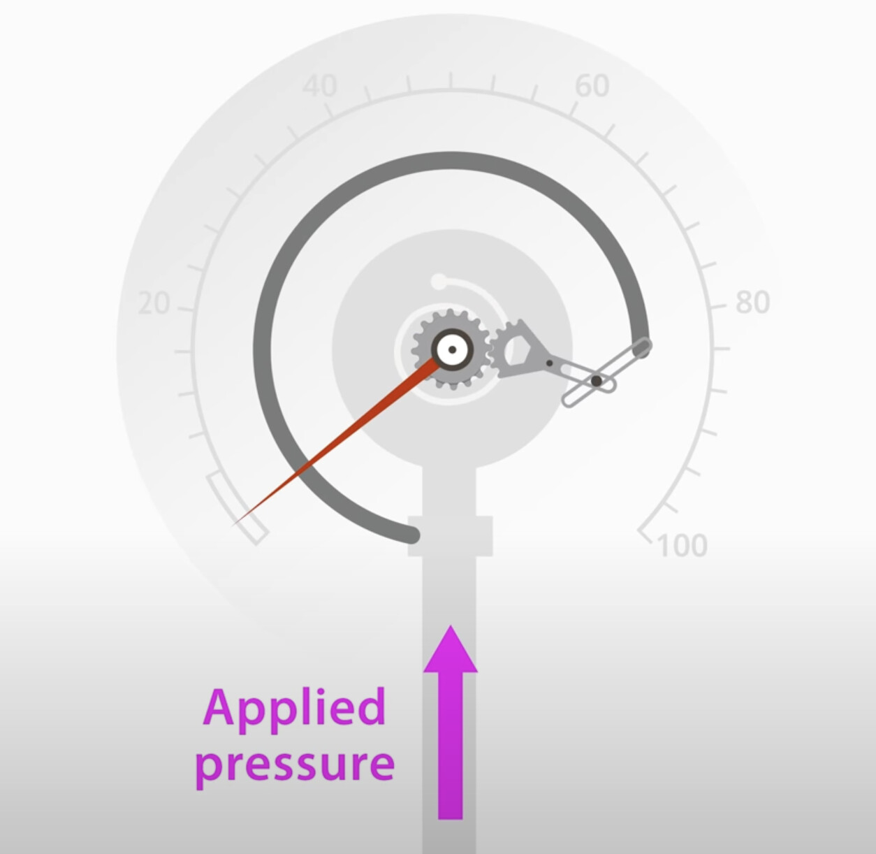
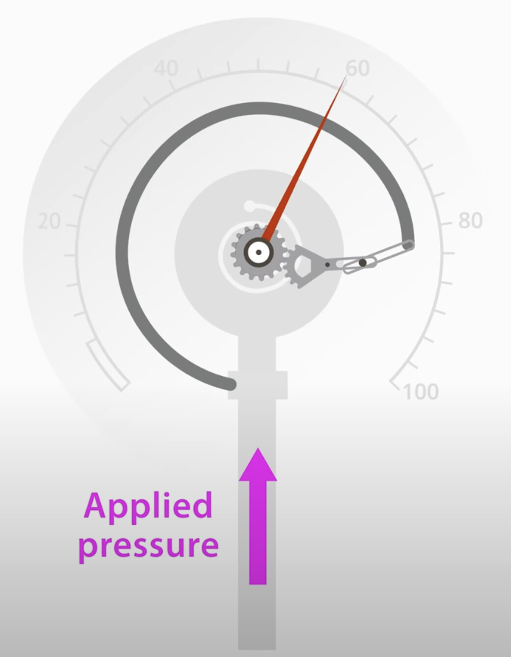
Source
In terms of deflection, if we take a “cut” of the coil we can see it’s basically a pressure vessel:
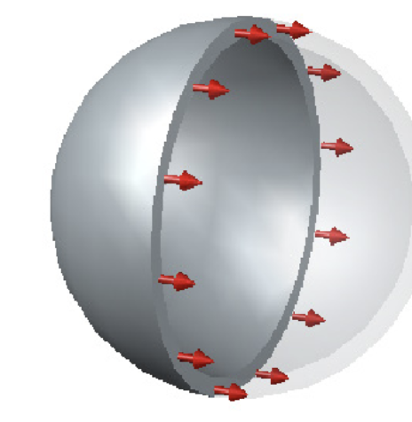
Source
So,
stress = (pressure*radius) / (2 * wall thickness)
Deflection is what gives us a reading in response to pressure so we can swap it out with stress=E*strain to get:
strain = (P*r) / (2*t*E)
All things equal, strain will vary with pressure. For the design aspect, if you want larger pressure readings you’ll probably want to reduce strain variation so increasing the thickness and young’s modulus while decreasing radius.
But for a more precise readings of pressure, you’ll probably want to decrease variables like young’s modulus so you can see a greater difference in strain in response to a small change in pressure.
The change in location of the coil’s end is what can generate that change in the dial’s location. I’d image the circumference is what’s directly related to the strain, so
C_new = C_original * (strain + 1)
The size of this pressure gauge can be user preference, and will likely dictate the bounds on the circumferences and thus strain. Likewise, the coil internal radius and thickness will likely be dictated by the size of the pressure gauge, so material and pressure range are parameters to be selected.
In terms of calibrating this pressure gauge, it looks like you can set the dial at zero since it’s joined through gears, so it becomes a matter of ensuring that change in the location of the coil’s end causes a range of about 270 degrees that the dial displays.
This will depend on the location of the pin (“pivot” below) that the gear that meshes with the dial’s gear rotates about. These distances will act as the ratio between how much the dial rotates and the linkage’s change is position.
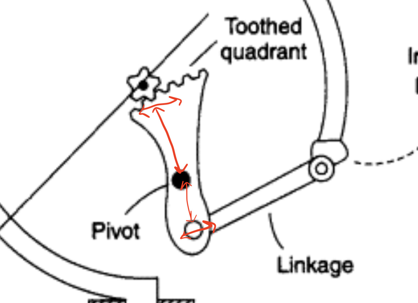
Source (marked up)