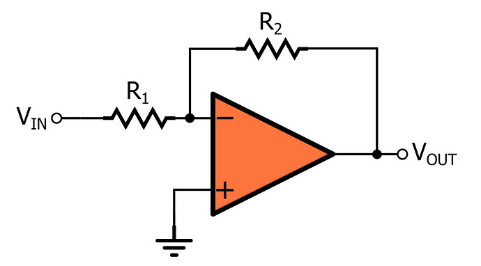
An inverting operational amplifier has the signal going in the inverting input pin. The closed feedback loop also connects back to the inverting pin, while the non-inverting pin is connected to ground.
The circuit for an inverting op amp looks as follows:
where the inverting op amp gain is:
A_v = Gain
If the input voltage was 1 V and gain is equal to -10, the output voltage would then be -10 V!
Working through the derivation of the gain formula:

Mathematically the voltage gain offered by the circuit is given as

Where,

However, we know that an ideal op amp has infinite input impedance due to which the currents flowing into its input terminals are zero i.e. I1 = I2 = 0. Thus, Ii = If. Hence,

We also know that in an ideal op amp the voltage at inverting and non-inverting inputs are always equal.
As we have grounded the non-inverting terminal, zero voltage appears at the non – inverting terminal. That means V2 = 0. Hence, V1 = 0, also. So, we can write

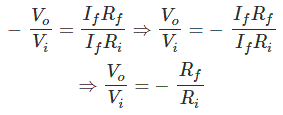
From, above two equations, we get,

The voltage gain of the inverting operational amplifier or inverting op amp is,

